Comparison of cycloid gears vs. planetary gears
For the use of precision gearboxes in robotics or automation, the designers are faced with the choice between two different gearbox designs: planetary and cycloid gearboxes. These each offer different advantages and disadvantages.
Cycloid and planetary gears are used in numerous different fields of application. The range of different gear types and designs from the leading manufacturers is correspondingly wide. For applications requiring particularly high precision – be it in plant engineering, robotics, machine tool construction or medical technology – robust precision gearboxes with a long service life are required. With planetary and cycloid gears, two different designs have become established here. In many cases, therefore, designers are faced with the challenge of recognising and weighing the respective advantages and disadvantages of these gear types in order to obtain the optimum reduction solution.

Planetary gears distribute the load
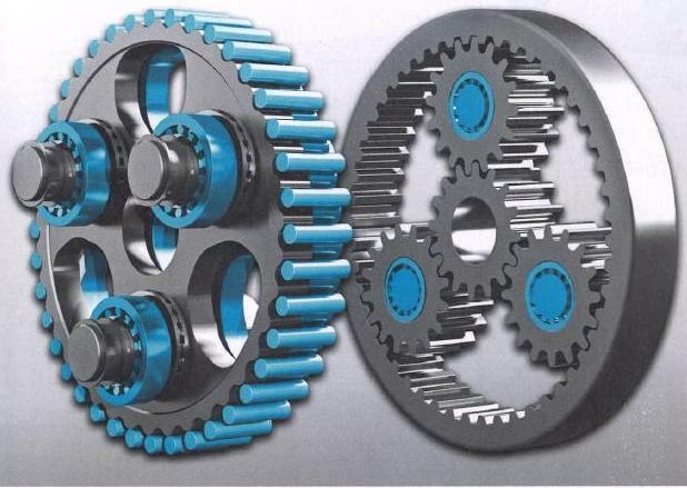
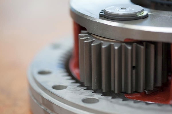
Planetary gears essentially consist of three basic elements: a central so-called sun gear, three or more satellite or planet gears and a ring gear. In a typical planetary gear, the sun gear transmits the movement to the satellites.
These then roll off in the static ring gear. The planetary gears are mounted on the planetary carrier, which then transmits the rotational speed to the output shaft. By supplementing one or more precursors, overall reduction could be further increased.
In contrast to simple reduction solutions, such as spur gears, lower forces act on the wheels in planetary gears, since the torque is always distributed among a plurality of gears. In addition, this distribution results in low-noise operation without interruption of the flow of force. The reduction ratio in a planetary stage is 3:1 to 10:1. For larger reductions, multi-stage gears are required.
Cycloid gear with two-stage reduction gear
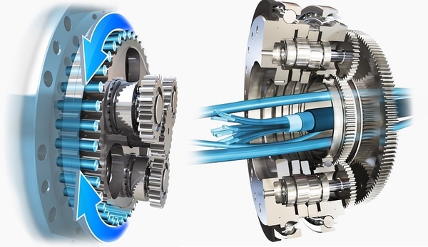
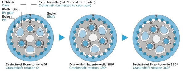
Cycloid gears, on the other hand, rely on two-stage drive components. They consist mainly of four components: a drive shaft, two to three eccentric shafts, two cam discs (RV discs) as well as a drive shaft that runs slowly corresponding to the reduction. First, in a first stage, the rotational movement of the servomotor is transmitted via the input shaft to the spur gears. In this case, the rotational speed is reduced in accordance with the reduction ratio of input shaft to spur gears. The spur gears are seated on eccentric shafts, which each have three eccentrics offset by 120°. The two cam plates are driven via needle bearings on the eccentrics. The three eccentric shafts are mounted in the drive shaft.


On the inside of the housing, a curve profile corresponding to the RV discs is incorporated. These form the second reduction stage. The curve profile in the housing has a greater depression than the RV discs. Bolts, which are arranged between the RV discs and the cam profile in the housing, transmit the rotational movement to the output shaft in a rolling manner. When the eccentric shafts undergo a full rotation, the cam discs continue to rotate eccentrically by one pitch. All curves of the cam disc touch the bolts and roll on them.
High torque with highest precision
A so-called toothed engagement is ensured over the entire circumference of the cam profile, since the two cam discs are displaced relative to one another by 180° on the eccentrics. In this way, very high torques can be transmitted with the highest precision and smooth running and high reduction ratios can be achieved due to the two reduction stages. Cycloid gearboxes allow reductions from 30:1 to over 300:1 – without additional precursors, as are otherwise necessary in planetary gearboxes.
Image source: © Nabtesco Precision Europe GmbH


